
Supply Chain Issues With Layflat Hose
Podcasts

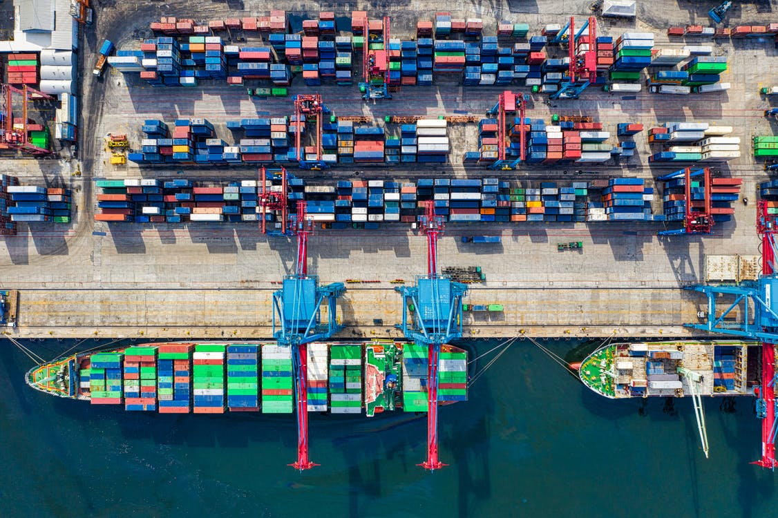
Supply Chain Issues For Layflat Hose

On this episode, I recap a great article from Flow magazine of The American Water Works Association.

The article details supply chain issues for layflat hose and how it has affected water, water plants, water distribution, and how that has an effect on our industry.

I share my takeaways and share that somehow we can prepare and manage the current supply chain issues.


Need Emergency Piping? http://bit.ly/3J0ASc9


Subscribe To The Podcast:

Apple Podcast | YouTube | Spotify


Connect With The Show:

Facebook | Linkedin | Website


About Isaac:

Chairman & Emergency Pipeline Advisor for Water, Wastewater, and Flood Management.

A UC Irvine graduate and beginning his career in safety and emergency supplies. Isaac was trained by David Jackson on all things related to PPS. With the help of his predecessor, he has updated PPS in regard to technology and processes. He believes that PPS has just started to make an impact.

PPS has usually been a west coast company but now Isaac believes that PPS can help utilities across the globe with PPS many applications. Not only with pipelines but with emergency response awareness as a whole. He enjoys sports, whiskey, and food.

About Portable Pipeline Systems:

We value preparation, trust, and integrity with our clients. We provide systems and solutions, not price only products. We encourage our clients to prepare in advance for the worst be it earthquake, flood, fires, or just an aging infrastructure.

At PPS we do not claim to have every solution for every disaster, we encourage clients to be open about their solutions and include all possible vendors. When in a disaster situation, a city, county, state, or government needs to consider all options.
 

Supply Chain Issues for Layflat Hose

Home sewage system
Emergency Response Systems for Water and Wastewater

Know The Technology Around You: How Sewer And Septic Systems Work To Make Your Life A Lot Better

Sewer and septic systems are EVERYWHERE around us, yet one of the questions I am asked most often is – how do they work?

Being in the business of water distribution and bringing wastewater from one place to another requires me to have a fairly good understanding about how sewer and septic systems work.

But I am constantly surprised about how little the common person understands the function of each system because these systems are in use every single day. Without them, we would literally be swimming in basins of wastewater no matter where we went.

Trust me, I get it – it’s not the most glamorous subject, but wastewater treatment and distribution is essential to our everyday life – and if you ever plan on buying either a home or business, you should have a working knowledge of how these systems work too. So let’s dive in!

Original article: https://home.howstuffworks.com/home-improvement/plumbing/sewer.htm

Why Do We Need a Sewer System?

Each time you flush the toilet or you wash something down the sink’s drain, you create sewage (also known in polite society as wastewater). One question that many people might ask is, “Why not simply dump this wastewater onto the ground outside the house, or into a nearby stream?” There are three main things about wastewater that make it something you don’t want to release into the environment:

  1. It stinks. If you release wastewater directly into the environment, things get very smelly very fast.
  2. It contains harmful bacteria. Human waste naturally contains coliform bacteria (for example, E. coli) and other bacteria that can cause disease. Once water becomes infected with these bacteria, it becomes a health hazard.
  3. It contains suspended solids and chemicals that affect the environment. For example:
    • Wastewater contains nitrogen and phosphates that, being fertilizers, encourage the growth of algae. Excessive algae growth can block sunlight and foul the water.
    • Wastewater contains organic material that bacteria in the environment will start decomposing. When they do, these bacteria consume oxygen in the water. The resulting lack of oxygen kills fish.
    • The suspended solids in wastewater make the water look murky and can affect the ability of many fish to breathe and see.
  4. The increased algae, reduced oxygen and murkiness destroy the ability of a stream or lake to support wildlife, and all of the fish, frogs and other life forms quickly die.

No one wants to live in an place that stinks, is full of deadly bacteria and cannot support aquatic life. That’s why communities build wastewater treatment plants and enforce laws against the release of raw sewage into the environment.­

Private Treatment: The Septic Tank

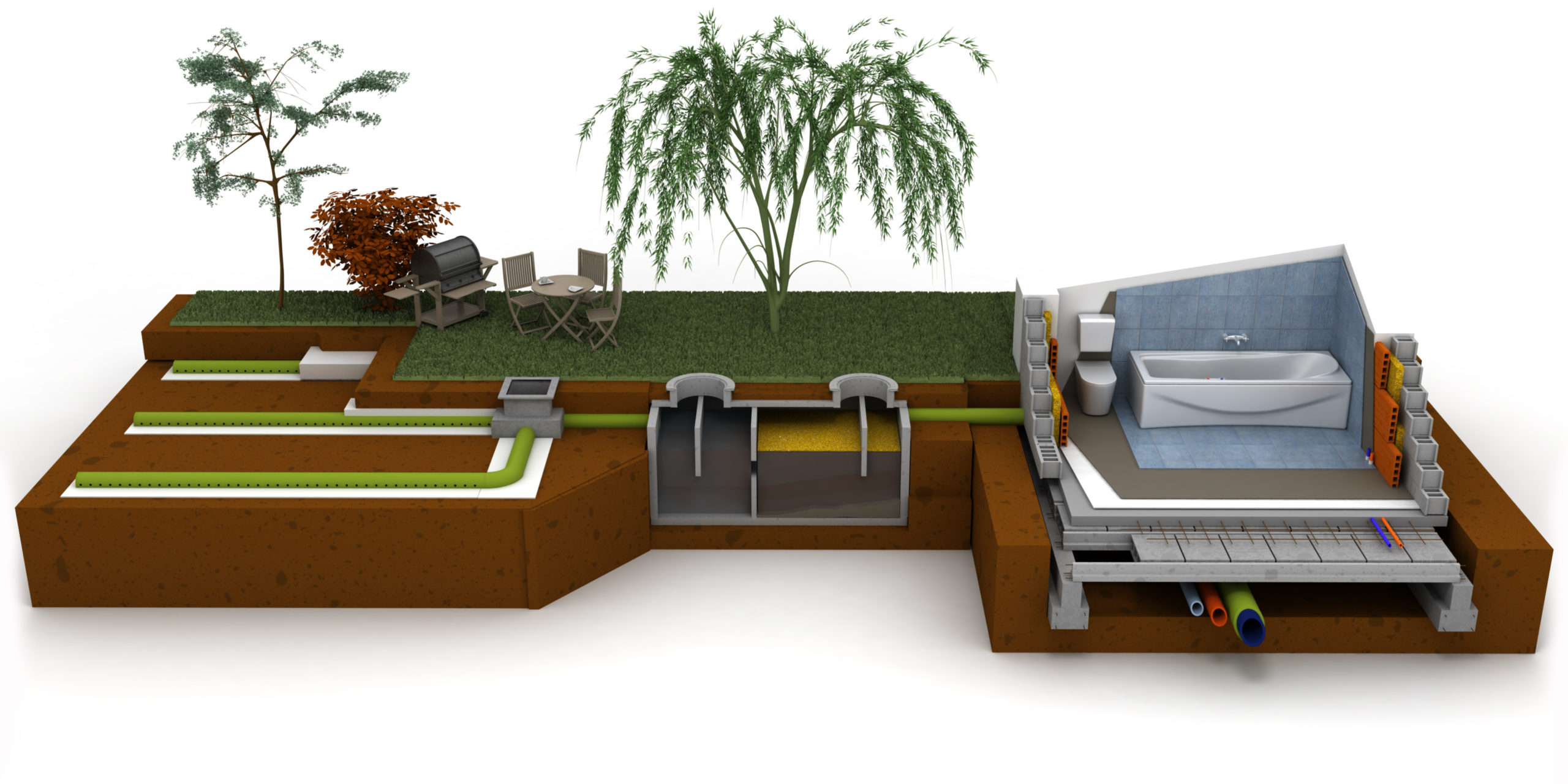
In rural areas where houses are spaced so far apart that a sewer system would be too expensive to install, people install their own, private sewage treatment plants. These are called septic tanks.

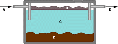
A septic tank is simply a big concrete or steel tank that is buried in the yard. The tank might hold 1,000 gallons (4,000 liters) of water. Wastewater flows into the tank at one end and leaves the tank at the other. The tank looks something like this in cross-section:

In this picture, you can see three layers. Anything that floats rises to the top and forms a layer known as the scum layer. Anything heavier than water sinks to form the sludge layer. In the middle is a fairly clear water layer. This body of water contains bacteria and chemicals like nitrogen and phosphorous that act as fertilizers, but it is largely free of solids.

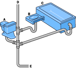
Wastewater comes into the septic tank from the sewer pipes in the house, as shown here:

A septic tank naturally produces gases (caused by bacteria breaking down the organic material in the wastewater), and these gases don’t smell good. Sinks therefore have loops of pipe called P-traps that hold water in the lower loop and block the gases from flowing back into the house. The gases flow up a vent pipe instead — if you look at the roof of any house, you will see one or more vent pipes poking through.

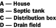
As new water enters the tank, it displaces the water that’s already there. This water flows out of the septic tank and into a drain field. A drain field is made of perforated pipes buried in trenches filled with gravel. The following diagram shows an overhead view of a house, septic tank, distribution box and drain field:

A typical drain field pipe is 4 inches (10 centimeters) in diameter and is buried in a trench that is 4 to 6 feet (about 1.5 m) deep and 2 feet (0.6 m) wide. The gravel fills the bottom 2 to 3 feet of the trench and dirt covers the gravel, like this:

The water is slowly absorbed and filtered by the ground in the drain field. The size of the drain field is determined by how well the ground absorbs water. In places where the ground is hard clay that absorbs water very slowly, the drain field has to be much bigger.

A septic system is normally powered by nothing but gravity. Water flows down from the house to the tank, and down from the tank to the drain field. It is a completely passive system.

You may have heard the expression, “The grass is always greener over the septic tank.” Actually, it’s the drain field, and the grass really is greener — it takes advantage of the moisture and nutrients in the drain field.

Urban Wastewater Systems

In urban and suburban areas where people are packed closer together and where there is a lot more wastewater to treat, the community will construct a sewer system that collects wastewater and takes it to a wastewater treatment facility.

In the ideal case, a sewer system is completely gravity-powered, like a septic system. Pipes from each house or building flow to a sewer main that runs, for example, down the middle of the street. The sewer main might be 3 to 5 feet (1 to 1.5 m) in diameter. Periodically, a vertical pipe will run up from the main to the surface, where it is covered by a manhole cover. Manholes allow access to the main for maintenance purposes.

The sewer mains flow into progressively larger pipes until they reach the wastewater treatment plant. In order to help gravity do its job, the wastewater treatment plant is usually located in a low-lying area, and sewer mains will often follow creekbeds and streambeds (which flow naturally downhill) to the plant.

Normally, the lay of the land will not completely cooperate, and gravity cannot do all the work. In these cases, the sewer system will include a grinder-pump or a lift station to move the wastewater up over a hill.

Once the water reaches the wastewater treatment plant, it goes through one, two or three stages of treatment (depending on the sophistication of the plant).

Here’s what each stage does:

  • The first stage, known as primary treatment, does the same thing a septic tank does. It allows the solids to settle out of the water and the scum to rise. The system then collects the solids for disposal (either in a landfill or an incinerator).
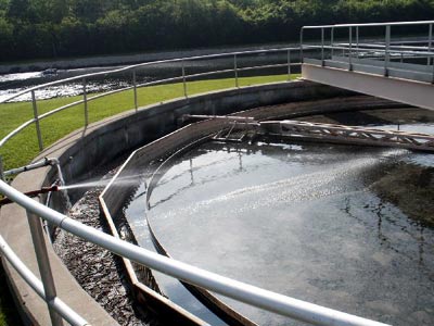
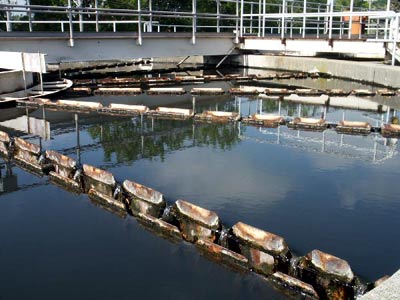
    Primary treatment is very simple — it involves a screen followed by a set of pools or ponds that let the water sit so that the solids can settle out.

  • Primary treatment might remove half of the solids, organic materials and bacteria from the water. If the plant does no more than primary treatment, then the water is chlorinated to kill the remaining bacteria and discharged.
  • The second stage, known as secondary treatment, removes organic materials and nutrients. This is done with the help of bacteria — the water flows to large, aerated tanks where bacteria consume everything they can.

  • The wastewater then flows to settling tanks where the bacteria settle out. Secondary treatment might remove 90 percent of all solids and organic materials from the wastewater.

  • he third stage, known as tertiary treatment, varies depending on the community and the composition of the wastewater. Typically, the third stage will use chemicals to remove phosphorous and nitrogen from the water, but may also include filter beds and other types of treatment. Chlorine added to the water kills any remaining bacteria, and the water is discharged.

Measuring the Effectiveness of a Treatment Plant

The effectiveness of wastewater treatment plants is measured on several different scales. Here are some of the most common:

  • pH – This is the measure of the water’s acidity once it leaves the plant. Ideally, the water’s pH would match the pH of the river or lake that receives the plant’s output.
  • BOD (bio-chemical oxygen demand) – BOD is a measure of how much oxygen in the water will be required to finish digesting the organic material left in the effluent. Ideally, the BOD would be zero.
  • Dissolved oxygen – This is the amount of oxygen in the water as it leaves the plant. If the water contains no oxygen, it will kill any aquatic life that comes into contact with it. Dissolved oxygen should be as high as possible and needs to cover the BOD.
  • Suspended solids – This is the measure of the solids remaining in the water after treatment. Ideally, suspended solids would be zero.
  • Total phosphorous and nitrogen – This is the measure of the nutrients remaining in the water.
  • Chlorine – The chlorine used to kill harmful bacteria needs to be removed so it does not kill beneficial bacteria in the environment. Ideally, chlorine should not be detectable.
  • Coliform bacteria count – This is the measure of fecal bacteria remaining in the water. Ideally, this number would be zero. Note that water in the environment is not totally free of fecal bacteria — birds and other wildlife do introduce some.

The main reason why these indicators need to be watched so closely is because any community produces a huge quantity of wastewater. Discharge levels ranging from 10 million to 100 million gallons per day (38 million to 380 million liters) are common for a wastewater treatment plant.

Be Safe – Think Ahead

At PPS, we value preparation, trust, and integrity with our clients. We provide systems and solutions, not price only products.  Though we do not claim to have every solution for every disaster, we encourage clients to be open about their solutions and include all possible vendors. When in a disaster situation, a city, county, state, or government needs to consider all options.
As such, we guide our clients to prepare in advance for the worst, be it earthquake, flood, fires, or just an aging infrastructure.

pexels-pixabay-40784
Emergency Response Systems for Water and Wastewater Potable Water

How To Get Drinking Water To The Right People Using Effecitve Drinking Water Distribution Systems

Water is essentially everywhere on and under Earth’s surface.  Fun fact though, less than 1 percent of it is liquid freshwater. In fact, most of Earth’s estimated 326 million cubic miles of water is in the oceans or frozen in polar ice caps and glaciers.

This is a little bit of an issue for water consumption because ocean water contains about 4.5 ounces per gallon of salts thus making it unfit for drinking.

This doesn’t mean we don’t have plenty of fresh water – we do!

But, as you can imagine, it’s not always available when and where it is needed. So, here’s the big question – how do we put drinking water in the hands of the people who need it?  We need effective drinking water distribution systems.

But first, let’s take a quick look at water sources, what it means for drinking water, and then we can dive into how we get it into the hands of the right people.

Surface water and groundwater

Surface water and groundwater are both important sources for community water supply needs. Groundwater is a common source for single homes and small towns, and rivers and lakes are the usual sources for large cities. Although approximately 98 percent of liquid fresh water exists as groundwater, much of it occurs very deep. This makes pumping very expensive, preventing the full development and use of all groundwater resources.

The hydrologic cycle

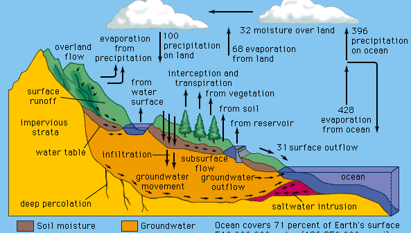
Water is in constant circulation, powered by the energy from sunlight and gravity in a natural process called the hydrologic cycle.

Water evaporates from the ocean and land surfaces, is held temporarily as vapour in the atmosphere, and falls back to Earth’s surface as precipitation. Surface water is the residue of precipitation and melted snow, called runoff. Where the average rate of precipitation exceeds the rate at which runoff seeps into the soil, evaporates, or is absorbed by vegetation, bodies of surface water such as streams, rivers, and lakes are formed. Water that infiltrates Earth’s surface becomes groundwater, slowly seeping downward into extensive layers of porous soil and rock called aquifers.

Under the pull of gravity, groundwater flows slowly and steadily through the aquifer. In low areas it emerges in springs and streams. Both surface water and groundwater eventually return to the ocean, where evaporation replenishes the supply of atmospheric water vapor.

Winds carry the moist air over land, precipitation occurs, and the hydrologic cycle continues.

Surface water sources

The total land area that contributes surface runoff to a river or lake is called a watershed, drainage basin, or catchment area. The volume of water available for municipal supply depends mostly on the amount of rainfall. It also depends on the size of the watershed, the slope of the ground, the type of soil and vegetation, and the type of land use.

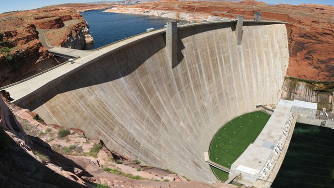
The flow rate or discharge of a river varies with time. Higher flow rates typically occur in the spring, and lower flow rates occur in the winter, though this is often not the case in areas with monsoon systems. When the average discharge of a river is not enough for a dependable supply of water, a conservation reservoir may be built. The flow of water is blocked by a dam, allowing an artificial lake to be formed.

Conservation reservoirs store water from wet weather periods for use during times of drought and low streamflow. A water intake structure is built within the reservoir, with inlet ports and valves at several depths. Since the quality of water in a reservoir varies seasonally with depth, a multilevel intake allows water of best quality to be withdrawn.

Sometimes it is advisable, for economic reasons, to provide a multipurpose reservoir. A multipurpose reservoir is designed to satisfy a combination of community water needs. In addition to drinking water, the reservoir may also provide flood control, hydroelectric power, and recreation.

Groundwater sources

The value of an aquifer as a source of groundwater is a function of the porosity of the geologic stratum, or layer, of which it is formed. Water is withdrawn from an aquifer by pumping it out of a well or infiltration gallery. An infiltration gallery typically includes several horizontal perforated pipes radiating outward from the bottom of a large-diameter vertical shaft.

Wells are constructed in several ways, depending on the depth and nature of the aquifer. Wells used for public water supplies, usually more than 30 metres (100 feet) deep and from 10 to 30 cm (4 to 12 inches) in diameter, must penetrate large aquifers that can provide dependable yields of good-quality water.

They are drilled using impact or rotary techniques and are usually lined with a metal pipe or casing to prevent contamination. The annular space around the outside of the upper portion of the casing is filled with cement grout, and a special sanitary seal is installed at the top to provide further protection. At the bottom of the casing, a slotted screen is attached to strain silt and sand out of the groundwater.

A submersible pump driven by an electric motor can be used to raise the water to the surface. Sometimes a deep well may penetrate a confined artesian aquifer, in which case natural hydrostatic pressure can raise the water to the surface.

Water requirements

Municipal water supply systems include facilities for storage, transmission, treatment, and distribution. The design of these facilities depends on the quality of the water, on the particular needs of the user or consumer, and on the quantities of water that must be processed.

Drinking-water quality

Water has such a strong tendency to dissolve other substances that it is rarely found in nature in a pure condition. When it falls as rain, small amounts of gases such as oxygen and carbon dioxide become dissolved in it; raindrops also carry tiny dust particles and other substances. As it flows over the ground, water picks up fine soil particles, microbes, organic material, and soluble minerals. In lakes, bogs, and swamps, water may gain colour, taste, and odour from decaying vegetation and other natural organic matter. Groundwater usually acquires more dissolved minerals than does surface runoff because of its longer direct contact with soil and rock. It may also absorb gases such as hydrogen sulfide and methane. In populated areas the quality of surface water as well as groundwater is directly influenced by land use and by human activities. For example, stormwater runoff contaminated with agricultural or lawn pesticides and fertilizers, as well as with road deicing chemicals or motor oil, can flow into streams and lakes. In addition, effluent from malfunctioning septic tanks and subsurface leaching fields can seep into groundwater.

Water quality standards set limits on the concentrations of impurities allowed in water. Standards also affect the selection of raw water sources and the choice of treatment processes. The development of water quality standards began in the United States in the early 20th century. Since that time, the total number of regulated contaminants has increased as toxicological knowledge and analytical measurement techniques have improved. Modern testing methods now allow the detection of contaminants in extremely low concentrations—as low as one part contaminant per one billion parts water or even, in some cases, per one trillion parts water. Water quality standards are continually evolving, usually becoming more stringent. As a result, the number of regulated contaminants increases over time, and their allowable concentrations in water are lowered.

Drinking-water regulations in the United States include two types of standards: primary and secondary.

Primary standards are designed to protect public health, whereas secondary standards are based on aesthetic factors rather than on health effects. Primary standards specify maximum contaminant levels for many chemical, microbiological, and radiological parameters of water quality. They reflect the best available scientific and engineering judgment and take into account exposure from other sources in the environment and from foods. Turbidity is also included in the primary standards because of its tendency to interfere with disinfection. Secondary standards are guidelines or suggested maximum levels of colour, taste, odour, hardness, corrosiveness, and certain other factors.

Municipal water consumption

Water consumption in a community is characterized by several types of demand, including domestic, public, commercial, and industrial uses. Domestic demand includes water for drinking, cooking, washing, laundering, and other household functions. Public demand includes water for fire protection, street cleaning, and use in schools and other public buildings. Commercial and industrial demands include water for stores, offices, hotels, laundries, restaurants, and most manufacturing plants. There is usually a wide variation in total water demand among different communities. This variation depends on population, geographic location, climate, the extent of local commercial and industrial activity, and the cost of water.

Water use or demand is expressed numerically by average daily consumption per capita (per person). In the United States the average is approximately 380 litres (100 gallons) per capita per day for domestic and public needs. Overall, the average total demand is about 680 litres (180 gallons) per capita per day, when commercial and industrial water uses are included. (These figures do not include withdrawals from freshwater sources for such purposes as crop irrigation or cooling operations at electric power-generating facilities.) Water consumption in some developing countries may average as little as 15 litres (4 gallons) per capita per day. The world average is estimated to be approximately 60 litres (16 gallons) per person per day.

In any community, water demand varies on a seasonal, daily, and hourly basis. On a hot summer day, for example, it is not unusual for total water consumption to be as much as 200 percent of the average demand. The peak demands in residential areas usually occur in the morning and early evening hours (just before and after the normal workday). Water demands in commercial and industrial districts, though, are usually uniform during the work day. Minimum water demands typically occur in the very early or predawn morning hours. Civil and environmental engineers must carefully study each community’s water use patterns in order to design efficient pumping and distribution systems.

Water distribution

A water distribution system is a network of pumps, pipelines, storage tanks, and other appurtenances. It must deliver adequate quantities of water at pressures sufficient for operating plumbing fixtures and firefighting equipment, yet it must not deliver water at pressures high enough to increase the occurrence of leaks and pipeline breaks. Pressure-regulating valves may be installed to reduce pressure levels in low-lying service areas. More than half the cost of a municipal water supply system is for the distribution network.

Pipelines

The pipeline system of a municipal water distribution network consists of arterial water mains or primary feeders, which convey water from the treatment plant to areas of major water use in the community, and smaller-diameter pipelines called secondary feeders, which tie in to the mains. Usually not less than 150 mm (6 inches) in diameter, these pipelines are placed within the public right-of-way so that service connections can be made for all potential water users. The pipelines are usually arranged in a gridiron pattern that allows water to circulate in interconnected loops; this permits any broken sections of pipe to be isolated for repair without disrupting service to large areas of the community. “Dead-end” patterns may also be used, but they do not permit circulation, and the water they provide is more susceptible to taste and odour problems because of stagnation.

A water distribution pipeline must be able to resist internal and external forces, as well as corrosion. Pipes are placed under stress by internal water pressure, by the weight of the overlying soil, and by vehicles passing above. They may have to withstand water-hammer forces; these occur when valves are closed too rapidly, causing pressure waves to surge through the system. In addition, metal pipes may rust internally if the water supply is corrosive or externally because of corrosive soil conditions.

Materials

Distribution pipes are made of asbestos cement, cast iron, ductile iron, plastic, reinforced concrete, or steel. Although not as strong as iron, asbestos cement, because of its corrosion resistance and ease of installation, is a desirable material for secondary feeders up to 41 cm (16 inches) in diameter. Pipe sections are easily joined with a coupling sleeve and rubber-ring gasket. Cast iron has an excellent record of service, with many installations still functioning after 100 years. Ductile iron, a stronger and more elastic type of cast iron, is used in newer installations. Iron pipes are provided in diameters up to 122 cm (48 inches) and are usually coated to prevent corrosion.

Underground sections are connected with bell-and-spigot joints, the spigot end of one pipe section being pushed into the bell end of an adjacent section. A rubber-ring gasket in the bell end is compressed when the two sections are joined, creating a watertight, flexible connection. Flanged and bolted joints are used for aboveground installations.

Plastic pipes are available in diameters up to 61 cm (24 inches). They are lightweight, easily installed, and corrosion-resistant, and their smoothness provides good hydraulic characteristics. Plastic pipes are connected either by a bell-and-spigot compression-type joint or by threaded screw couplings.

Precast reinforced concrete pipe sections up to 366 cm (12 feet) in diameter are used for arterial mains. Reinforced concrete pipes are strong and durable. They are joined using a bell-and-spigot-type connection that is sealed with cement mortar. Steel pipe is sometimes used for arterial mains in aboveground installations. It is very strong and lighter than concrete pipe, but it must be protected against corrosion with lining of the interior and with painting and wrapping of the exterior. Sections of steel pipe are joined by welding or with mechanical coupling devices.

Fittings

In order to function properly, a water distribution system requires several types of fittings, including hydrants, shutoff valves, and other appurtenances. The main purpose of hydrants is to provide water for firefighting. They also are used for flushing water mains, pressure testing, water sampling, and washing debris off public streets.

Many types of valves are used to control the quantity and direction of water flow. Gate valves are usually installed throughout the pipe network. They allow sections to be shut off and isolated during the repair of broken mains, pumps, or hydrants. A type of valve commonly used for throttling and controlling the rate of flow is the butterfly valve. Other valves used in water distribution systems include pressure-reducing valves, check valves, and air-release valves.

Installation

Water mains must be placed roughly 1 to 2 metres (3 to 6 feet) below the ground surface in order to protect against traffic loads and to prevent freezing. Since the water in a distribution system is under pressure, pipelines can follow the shape of the land, uphill as well as downhill. They must be installed with proper bedding and backfill. Compaction of soil layers under the pipe (bedding) as well as above the pipe (backfill) is necessary to provide proper support. A water main should never be installed in the same trench with a sewer line. Where the two must cross, the water main should be placed above the sewer line.

Pumps

Many kinds of pumps are used in distribution systems. Pumps that lift surface water and move it to a nearby treatment plant are called low-lift pumps. These move large volumes of water at relatively low discharge pressures. Pumps that discharge treated water into arterial mains are called high-lift pumps. These operate under higher pressures. Pumps that increase the pressure within the distribution system or raise water into an elevated storage tank are called booster pumps. Well pumps lift water from underground and discharge it directly into a distribution system.

Most water distribution pumps are of the centrifugal type, in which a rapidly rotating impeller adds energy to the water and raises the pressure inside the pump casing. The flow rate through a centrifugal pump depends on the pressure against which it operates. The higher the pressure, the lower the flow or discharge. Another kind of pump is the positive-displacement type. This pump delivers a fixed quantity of water with each cycle of a piston or rotor. The water is literally pushed or displaced from the pump casing. The flow capacity of a positive-displacement pump is unaffected by the pressure of the system in which it operates.

Storage tanks

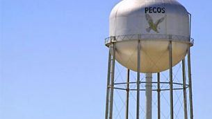
Distribution storage tanks, familiar sights in many communities, serve two basic purposes: equalizing storage and emergency storage. Equalizing storage is the volume of water needed to satisfy peak hourly demands in the community. During the late night and very early morning hours, when water demand is lower, high-lift pumps fill the tank. During the day, when water demand is higher, water flows out of the tank to help satisfy the peak hourly water needs. This allows for a uniform flow rate at the treatment plant and pumping station. Water in a distribution storage tank may also be needed for fighting fires, cleaning up accidental spills of hazardous materials, or other community emergencies. The capacity of a distribution storage tank is designed to be about equal to the average daily water demand of the community.

Distribution storage tanks are built at ground level on hilltops higher than the service area. In areas with flat topography, the tanks may be elevated aboveground on towers in order to provide adequate water pressures, or ground-level storage tanks with booster pumping may be provided.


Be Safe – Think Ahead

At PPS, we value preparation, trust, and integrity with our clients. We provide systems and solutions, not price only products.  Though we do not claim to have every solution for every disaster, we encourage clients to be open about their solutions and include all possible vendors. When in a disaster situation, a city, county, state, or government needs to consider all options.
As such, we guide our clients to prepare in advance for the worst, be it earthquake, flood, fires, or just an aging infrastructure.

Isaac Alatorre
Podcasts

Meet Your Host Issac Alatorre

Get to know your host Isaac Alatorre as he chats with Chris Revill (Simplified Impact) about how Isaac got into the utility industry, what lead Isaac to purchase Portable Pipeline Systems from David W. Jackson, what we can expect from future episodes, and what Isaac likes to do in his free time.

Need Emergency Piping? http://bit.ly/3J0ASc9


Subscribe To The Podcast:

Apple Podcast | YouTube | Spotify


Connect With The Show:

Facebook | Linkedin | Website


About Isaac:

Chairman & Emergency Pipeline Advisor for Water, Wastewater, and Flood Management.

A UC Irvine graduate and beginning his career in safety and emergency supplies. Isaac was trained by David Jackson on all things related to PPS. With the help of his predecessor, he has updated PPS in regard to technology and processes. He believes that PPS has just started to make an impact.

PPS has usually been a west coast company but now Isaac believes that PPS can help utilities across the globe with PPS many applications. Not only with pipelines but with emergency response awareness as a whole. He enjoys sports, whiskey, and food.

About Portable Pipeline Systems:

We value preparation, trust, and integrity with our clients. We provide systems and solutions, not price only products. We encourage our clients to prepare in advance for the worst be it earthquake, flood, fires, or just an aging infrastructure.

At PPS we do not claim to have every solution for every disaster, we encourage clients to be open about their solutions and include all possible vendors. When in a disaster situation, a city, county, state, or government needs to consider all options.
Utility Emergency Response Podcast
Podcasts

Welcome to Utility Emergency Response

Meet your host Isaac Alatorre Chairman & Emergency Pipeline Advisor for Water, Wastewater, and Flood Management. In this introductory episode Issac shares what’s in store for the future of Welcome to Utility Emergency Response.

Need Emergency Piping? http://bit.ly/3J0ASc9


Subscribe To The Podcast:

Apple Podcast | YouTube | Spotify


Connect With The Show:

Facebook | Linkedin | Website


About Isaac:

Chairman & Emergency Pipeline Advisor for Water, Wastewater, and Flood Management.

A UC Irvine graduate and beginning his career in safety and emergency supplies. Isaac was trained by David Jackson on all things related to PPS. With the help of his predecessor, he has updated PPS in regard to technology and processes. He believes that PPS has just started to make an impact.

PPS has usually been a west coast company but now Isaac believes that PPS can help utilities across the globe with PPS many applications. Not only with pipelines but with emergency response awareness as a whole. He enjoys sports, whiskey, and food.

About Portable Pipeline Systems:

We value preparation, trust, and integrity with our clients. We provide systems and solutions, not price only products. We encourage our clients to prepare in advance for the worst be it earthquake, flood, fires, or just an aging infrastructure.

At PPS we do not claim to have every solution for every disaster, we encourage clients to be open about their solutions and include all possible vendors. When in a disaster situation, a city, county, state, or government needs to consider all options.
San Diego Water
Case Study

San Diego Water Utilties

Project Details

During a construction project a 36” Concrete pressure main was being installed when the line supplying water to the El Camino Memorial Funeral Park was severed.
Client San Diego Water Utilities
SiteNorth San Diego County, Mira Mesa Blvd. & Carroll Road
Product800’ (8/100’) lengths of 2-112″ Portable Pipeline coupled with Cast Brass Fire Hose couplings NPSH threads
Date December 28, 1998


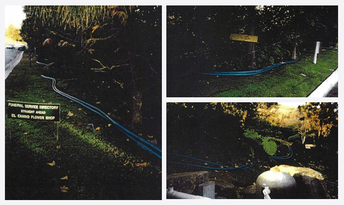
On the 21st of December the Field Utility Supervisor responded to a call from the El Camino Memorial Funeral Park that they had lost their water supply. Upon investigation, it was determined that a construction co. was installing a new 36″ concrete pressure main along Carroll Rd. This road leads to the El Camino Memorial Park. During excavation they accidentally severed the primary water main to the Memorial Park.

The distribution division of SDWD responded to the incident by bringing out (8/100′) lengths of 2-112″ Portable Pipeline from their Emergency Response storeroom. Each length was coupled with Cast Brass Expansion Ring NPSH threaded couplings. Two parallel lines of 2-1/2″ Portable Pipeline were laid above ground along the road leading to the Memorial Park’s intake manifold.

The Park requires a constant supply of water at approximately 80 lbs. The volume needed and pressure supplied by SDWD was sufficient to operate all lawn sprinklers, decorative fountain systems and still maintain an adequate supply of water to operate the sanitation facilities.

The quick response on the part of SDWD permitted the Memorial Park to remain open for visitations and maintain their scheduled memorial services.

The San Diego Water Department considers the Portable Pipeline System to be a “good investment” and they plan to purchase additional sizes and lengths in the future.

Factory: 910 E. Noble Way Santa Mtll’ia, CA 93454  Tel: 800-747–7075 Fax: 805-922–0086

Field Office: 3844 Mistral Dr. Huntington Beach, CA. 92649 Tel: 714-840-3740 Fax: 714-840-1434 Pg: 800-504-2514

LADWP
Case Study

LADWP Testimonial

Project Details

Date:        August 15, 2000
To:        Whom It May Concern
From:       David W. Jackson
Re:          Los Angeles Dept of Water & Power
Location:    Central Division Yard – LADWP
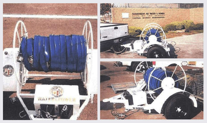
Situation:    LADWP Central Yard purchased a single Axle small diameter reel system for the storage, deployment and retrieval of potable water hose for Hi-Lining operations.


The Central Yard of the Los Angeles Department of Water and Power purchased 500′ of 2″ Blue Portable Pipeline to be prepared for potential earth quake damage to water service in their area. They chose to purchase 100 foot lengths of Portable Pipeline and had each length coupled with Aluminum CamLok ends. The reel system was re-worked so all 2″ Blue Portable Pipeline with appropriate end couplings, adapters and fittings could be loaded on the reel system and transported to the job site at one time.

Because of its size and simplicity of operation the complete Hose Reel system is ready to respond to water main outages on a timely basis.

The maintenance personnel consider the HR Potable Water System to be an asset for the Central Yard and expect to purchase additional lengths of Portable Pipeline hose in 2-1/2″ size in 2002. When additional lengths are purchased they plan to modify the reel to include dividers and enlarge the system to accommodate additional sizes and lengths.


Portable Pipeline Systems

Field Office: 3844 Mistral Dr. Huntington Beach, CA. 92649   Tel: 714-840–3740   Fax: 714-840-1434   Pg: 800-504-2514

Lake Elsinore Municipal Water District
Case Study

Lake Elsinore Municipal Water District

Project Details

Date:    October 19, 2004
To:   Whom It May Concern
From:   David W.Jackson
Re:           Lake Elsinore Municipal Water District (photo attached)
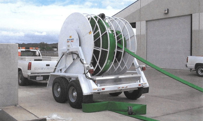
Situation:                Installation of 3000′ 6″ Wasteline 600 Green on HR6 Hose Reel System

Robert Bernard Operations Manager and Keith Ray Lift Station Field Supervisor for the Lake Elsinore Municipal Water District made an evaluation and assessment of equipment needed to respond to emergency sewer spills. This equipment was needed due to the sensitive environmental situation in the Lake Elsinore recreational area to any sewer line breakage and potential discharge of sewerage into the lake.

The basic component for this Emergency Preparedness response system was the HR-6 Hose Reel System. It was designed specifically for the Transport, Deployment, Retrieval and Storage of at least 3000 feet of 6″ sewer bypass hose. This system would permit the Sewer operations department to respond to sewer spills on a timely basis with enough equipment to bypass sewerage to other sewer lines while the plugged sewer line is being cleared of debris.

The Lake Elsinore Municipal  Water District feels the purchase of the HR–6 Hose Reel System with 3000 feet of 6″ Wasteline 600 Green is the foundation for their Emergency Preparedness System. They expect to add of this base system as needed and feel that being prepared to meet the emergency needs of their area is an investment in maintaining a clean and safe environment for the present and future needs of the residents and visitors to the Lake Elsinore recreational area.

Wasteline 600 Green is available in sizes from 2” through 12″ and in lengths up to 660 feet. Wasteline 600 Green can be cut easily to meet various length requirements especially in emergency field operations where specific lengths may be needed. Field Attachable (FA6Stz)* 6” Storz end fittings are attached by using common razor knives to cut hose and socket wrenches to secure the three (3) piece attaching collars. Adapters can also be provided to connect the Storz ends to pump discharge threaded end fittings.

 *Storzfittings available in 4″, 6″, 8“size, pressure rated at 400 lbs and require no wrenches to connect

Portable Pipeline Systems

Field Office: 3844 Mistral Dr. Huntington Beach, CA.  92649  Tel: 714-840–3740  Fax: 714–840-1434


City of Huntington Beach
Case Study

City of Huntington Beach

Project Details

Date:                March 1, 2000
To:                Whom It May Concern
From:                David W. Jackson
Re:                Huntington Beach Water Dept.
Location:     City of Huntington Beach
Site:                          Strip Shopping Mall on Comer of Warner Blvd and Golden West Blvd
Situation:                 The City of Huntington Beach Water Dept was called out in response to the loss of water caused from a contractor breaking the underground water main. This main supplied water to all the businesses in the mall.
Product:                   500′  (4/100′)  and  (2/50′)  lengths  of  2-1/2″  Portable  Pipeline  w/NSF-61 certifications coupled with Aluminum Fire Hose threaded ends.

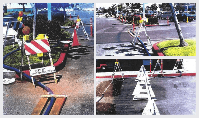
Huntington Beach  Water chose to use their 2-1/2” Portable Pipeline System due to flow requirements from businesses in a strip mall shopping area. They installed the various lengths of 2-1/2″ AquaMan Blue inabout an hour.

The HB Water purchased the Portable Pipeline System due to potential damage from earthquakes in their water system. They recognized the need to have an above the ground temporary certified water lines to “Hi-Line“over broken underground water mains.

Due high traffic and potential tire damage to the 2-1/2″ (PPS) they also deployed one set of 3JHR road ramps. The 3JHR were designed to protect 3” and smaller diameter hoses. The 3JHR’s are manufactured from steel with interlocking connectors to prevent accidental separation. The 3JHR cover  12 feet of road surface or a single lane of traffic. The Water Department installed two sets of the 3JHR’s on the main entrance and exits to the mall.

The Huntington Beach Water Dept. plans to purchase additional lengths of 2-112″ AquaMan Blue as needed.

Factory:  910 E. Noble Way Santa Maria, CA. 93454   Tel: 800-747-7075  Fax: 805-922-0086

Field Office: 3844 Mistral Dr. Huntington Beach, CA. 92649  Tel: 714-840-3740 Fax: 714-840-1434  Pg: 800-504-2514


City of Freemont
Case Study

City of Freemont Testimonial

Project Details

Date:        December 15, 1998
To:        Whom It May Concern
From:      David W. Jackson
Re:        Alameda County Water Department (ACWD)- Fremont, California
Location:         City of Fremont, California.
Site:                 Mission Road -Deep Creek Apartments (photo attached)
Situation:            The Deep Creek apartment complex in the City of Fremont lost it water source because a contractor broke the water line. The ACWD responded to the situation with a temporary 6″ Portable Pipeline.
Product:                (5/100′) lengths of 6″ Portable Pipeline with Field Attachable Cast Aluminum fitting with Victaulic ends.

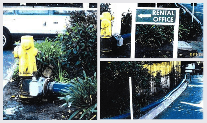
In mid December 1998 ACWD received notice that the 6″ water main providing water to the multi-family residents in the Deep Creek Apartment complex had broken. In response to the emergency, ACWD chose to deploy some of its recently purchased 6″ Portable Pipeline.

ACWD attached the 6″ Blue Portable Pipeline to a Fire Hydrant. The ACWD used an 8″ X 6″ Cast Iron Flanged Tee, a 6″ gear operated Butterfly Valve and a 6″ Style 741 Victaulic X flange adapter. By using these fittings the water department attached the Portable Pipeline to the hydrant without having to interrupt the Fire Department connection. ACWD deployed the Portable Pipeline on the top of the curb area thereby avoiding any potential damage from automobile tires or impeding traffic movement.

ACWD kept the temporary line in service for approximately two weeks while the contractor repaired the underground cast iron main. Using the PPS tool permitted the apartment complex to have all the water they needed yet permitted ACWD to work normal job schedules without having to pay overtime.

ACWD considers the Portable Pipeline System an investment and valuable asset in their emergency preparedness program. They consider the PPS as a critical tool in their water main construction repair program.

Factory: 910 E.Noble Way Santa Maria, CA. 93454 Tel: 800-747–7075Fax: 805-912-0086

Field Offu:e: 3844 Mistral Dr. Huntington Beach, CA. 92649 Tel· 714-840-3740 Fax: 714-840-1434 Pg: 800-504-2514